Building Parallel Port Boxes
| There are multiple ways to control Christmas lights via a Computer. If you are just getting started, using the Parallel port is a good starting point in my opinion. (X-10 is another option. X-10 is probably a little cheaper and easier, but there are issues with speed and scalability.) With just a little bit of electrical knowledge and some fairly common equipment, you can control up to 8 circuits per parallel port (max of 3 ports per computer) without needing to know anything about integrated circuits. Plus, if you do plan to upgrade to a more complex parallel port control method (or use digital I/O boards), all you need to do is change out the 5Vdc interface and these boxes are ready to go in your new environment. |

|
The Parts
| Solid State Relays (SSRs) | I use 10A 120V Relays. You can usually find them for $3-$10 a piece, used. You'll need 8 of them. Since you local hardware probably doesn't carry these, you might want to check out All Electronics or MJPA, Inc | $40 |
| Bulk Wire (14 gauge) | 5 feet of black, 5 feet of white is plenty. I usually find this at about $.10/ft | $1 |
| 14-3 Wire (I prefer Rubber coated.) | $.60/ft or so. Depends on what you get. 10ft or less. | $6 |
| Pig Tail (14 gauge) | Be careful. Don't go smaller that 14 Gauge. If you shop around you can usually find a good deal on these. Alternatively, you can make your own. | $3 |
| Crimp Connectors | These are really optional. I just prefer them to wrapping wires around terminals. | $5 |
| Machine Bolts with nuts | Or something else for connecting your SSRs to your project box. | $5 |
| 120V Indicator (optional) | Lots of people place these on each box they build. I personally just have 8 wired to some electrical plugs for debugging. That way I can easily move them from box to box for testing SSRs. | $8 |
| 1/2" Wire clamps | Depending on your exact configuration, you might use 5-10 of these guys. (The are used for clamping the wires to your project and metal boxes.) A bag of 10 cost about $6. | $6 |
| two 4x4 electrical boxes to hold the outlets | Cost will depend on meta vs. plastic. My metal boxes with covers cost about $4.50 a piece. | $8 |
| 4 outlets | White, brown, black, whatever | $4 |
| Box to hold the SSRs | Projects boxes can really range in price. I got lucky and found a number of perfectly sized boxes for $1.50 a piece. Normally, I would pay $8-$20 for a x-large Project box. | $12 |
| DB-25 Wire | As long as one end fits the computer, it really doesn't matter what is on the other end. (Your going to cut it off unless of course you want to solder a connector onto your control box.) | $5 |
| Tools | Screw Divers, Drill (doesn't need to be power), pliers, wire stripping/crimping tool, knife, and an ohms meter all assisted me. | - |
| Total: | ~ $100 | |
$100 is probably a a high water mark. Buying in bulk or shop around for deals can really lower the price. Also, SSRs can be built a lot cheaper than they can be purchased, but that requires some knowledge of integrated circuits; something this how-to is trying to avoid.
Standard disclaimer: I'm not responsible for anyone hooking these circuits
up and the results that follow their use.
Schematic
Here is the end wiring result. Pins 2-9 are the control (positive) wires going to the box., while pins 18-25 can all be used for grounding.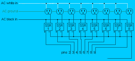
Solid State RelaysSolid State Relays (SSRs) are the heart of Parallel Port Control Boxes. I find it easier to purchase pre-built SSRs, but you can build them (rather cheaply) if you know what your doing. Drew Hickman provides some good information on his Christmas site for building SSRs. If you shop around, you can usually find used 110V 10A SSRs that will work with 5 vdc input for under $5 a piece (sometimes $3).All a Solid State Replay really does is allow the 110V AC current to pass through when 3-8V DC is applied, and opens the AC circuit when the direct current is not present. |

|
Relay BoxesYou'll need a box (plastic or metal, it really doesn't matter) to hold your eight solid state relays. I've seen others use large boxes (14" x 14") and some (like me) use small (9" x 5" x 1.5") boxes. I found a good deal at All Electronics on some used boxes ($1.50), so I went with those. |
|
Electrical BoxesYou'll need an electrical box or two (I recommand metal) to hold your outlets. If you look at the way the outlets are wired, you notice that the NEUTRAL (right side) of each outlet is connected together. For the NEUTRAL side, it is important that the tabs between the top and bottom outlet are not broken, but since we want each outlet to be controlled individually, the tab on the hot (left side) is broken.I used 14-3 rubber coated wire because
Note: It would have been nice if 10 wires could have been easily brought in so that a common ground wire could have been used to ground the entire box. This can be accomplished by having the 110V pig tail that brings the AC current from your house, go directly into the boxes that hold the outlets rather than into the box that holds the relays. If wired this way, the ground and NEUTRAL wires from the pig tail can be connect to one of the outlets and then the hot (black) wire could be sent up to the relay box though on of the nine wires that connect the outlets to the relay box. In that case, 8 of the 9 wires could carry the individual hot circuits down to the outlets, and the other wire would care the common hot circuit up to the relay box. Unfortunately, I build my demo box before thinking of this solution. |


|
The ToolsIt doesn't take very many tools to put all of this together. All you really need is a few screwdrivers, a knife, wire scripts, electrical meter (testing), pliers, and possible a drill for drilling holes in your relay box. |

|
The Wired Relay BoxWhen wiring the relays into the box, the NEUTRAL terminals of the low voltage side can all be wired together (white wire). (I really should have used a much smaller wire since only 5vdc is being carried across, but I didn't have any handy. Surprisingly, the voltage drop by using 14 gauge wire is hardly noticeable.)The incoming terminals of 110V AC sides can all be wired together too (black wire). This way 110V is available at each SSR, ready to be switch on. If you want to include indicator lights in your boxes, make sure you get 120V indicators and connect them across the 120V AC side of your SSR. It is better to do it this way rather than using a low volage LED because (1) the indicator won't light if the SSR burns out, and (2) you aren't pulling amps from the computer's power supply to power to indicators. |


|
The Control WiresThe last piece of the puzzle is adding the control wires for the parallel port. All I did is take a printer cable, and cut off the end that goes to the printer. Pins 2-9 on the parallel port cable should go to the individual SSRs (HOT side)and the ground wire (usually back with white stripe) should connect to the NEUTRAL side of the SSRs. |

|
Controlling the Interface
|
If you are not interested in rolling your own software, check out
Vixen. The Basic Parallel plug-in
works just fine with this design.
Controlling the parallel port interface is really easy. Each of the 8 bits controls a circuit. Each bit has a number (bit 1=1, bit 2=2, bit 3=4, bit 4=8, bit 5=16, bit 6=32, bit 7=64, bit8=128). The only other piece of information you need is the I/O address for the parallel port. Normally, this is port 0x378 (888 in base 10). To turn on bits 3, 4, and 6 the basic code would be:
out 888, 44 '4+8+32 = 44
Some sample QBasic code is listed to the right. If you have Win3.1 or Win95, QBasic should automatically be installed on your PC. If you have a new version of windows, you can download a program called "First Basic" from http://www.qbasic.com/c1.shtml Note: New versions of Windows (> 3.1) don't allow direct control of the parallel port just by writing to the memory address. For Windows 95/98, your best bet is to boot your machine into DOS mode (opening up a DOS window while Windows is still running won't work.) For Windows NT, 2000, or XP, controlling the parallel port is even more difficult. Initially, at least, I recommend making a DOS 5.0 boot disk, booting your machine into DOS 5.0, and using QBasic to test your device. There are utilities available via the web (such as The BootDisk Project for creating old Boot disk. Once you get your device working via that method, you can either build your entire program in QBasic and run your computer from a boot disk, or you can look into more complicated solutions that actually working while windows is running. (More information on those to be posted soon.) |
'Parallel port 1 is port 888 |

|

|
|
|
|
|
Greg & Mary Hormann ghormann@gmail.com http://www.thehormanns.net |
Copyright © 2000-2023 All Rights Reserved |
|
|
|